原廠連結:https://docs.particle.io/datasheets/photon-datasheet/
Model number: PHOTONH, PHOTONNOH
void setup() {
    Particle.publish("my-event","The internet just got smarter!");
}
Functional description
OVERVIEW
Particle's Internet of Things hardware development kit, the Photon, provides everything you need to build a connected product. Particle combines a powerful ARM Cortex M3 micro-controller with a Broadcom Wi-Fi chip in a tiny thumbnail-sized module called the PØ (P-zero).
To get you started quickly, Particle adds a rock solid 3.3VDC SMPS power supply, RF and user interface components to the PØ on a small single-sided PCB called the Photon. The design is open source, so when you're ready to integrate the Photon into your product, you can.
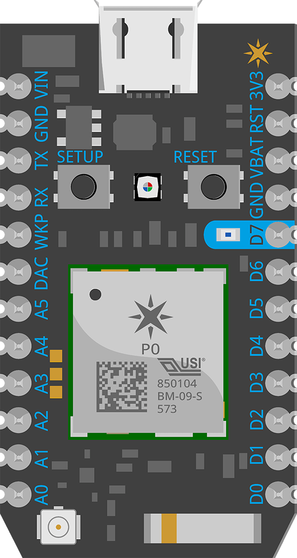
The Photon comes in two physical forms: with headers and without. Prototyping is easy with headers as the Photon plugs directly into standard breadboards and perfboards, and may also be mounted with 0.1" pitch female headers on a PCB. To minimize space required, the Photon form factor without headers has castellated edges. These make it possible to surface mount the Photon directly onto your PCB.
FEATURES
- Particle PØ Wi-Fi module
- Broadcom BCM43362 Wi-Fi chip
- 802.11b/g/n Wi-Fi
- STM32F205 120Mhz ARM Cortex M3
- 1MB flash, 128KB RAM
- On-board RGB status LED (ext. drive provided)
- 18 Mixed-signal GPIO and advanced peripherals
- Open source design
- Real-time operating system (FreeRTOS)
- Soft AP setup
- FCC, CE and IC certified
Interfaces
BLOCK DIAGRAM
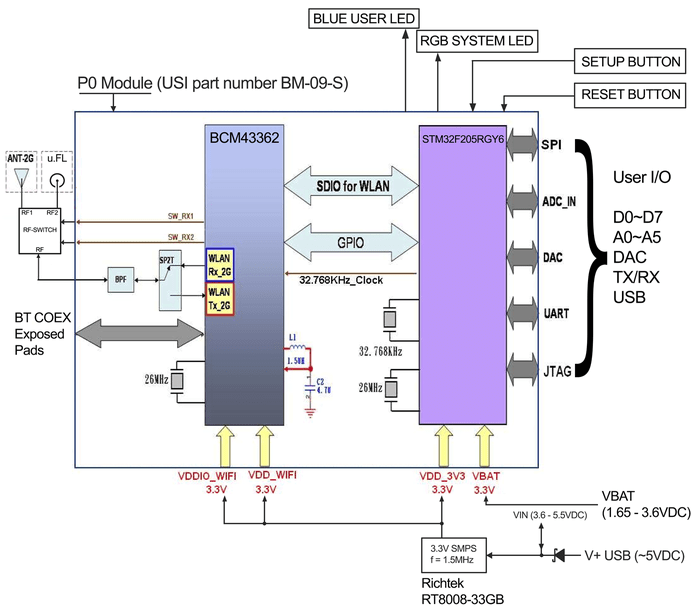
POWER
Power to the Photon is supplied via the on-board USB Micro B connector or directly via the VIN pin. If power is supplied directly to the VIN pin, the voltage should be regulated between 3.6VDC and 5.5VDC. When the Photon is powered via the USB port, VIN will output a voltage of approximately 4.8VDC due to a reverse polarity protection series schottky diode between V+ of USB and VIN. When used as an output, the max load on VIN is 1A.
Typical current consumption is 80mA with a 5V input. Deep sleep quiescent current is 160uA. When powering the Photon from the USB connector, make sure to use a quality cable to minimize IR drops (current x resistance = voltage) in the wiring. If a high resistance cable (i.e., low current) is used, peak currents drawn from the Photon when transmitting and receiving will result in voltage sag at the input which may cause a system brown out or intermittent operation. Likewise, the power source should be sufficient enough to source 1A of current to be on the safe side.
RF
The RF section of the Photon is a finely tuned impedance controlled network of components that optimize the efficiency and sensitivity of the Wi-Fi communications.
An RF feed line runs from the PØ module into a SPDT RF-switch. Logic level control lines on the PØ module select which of the two ports of the RF-switch is connected to the RF feed line. A 100pF decoupling capacitor is located on each control line. One port is connected to a PCB ceramic chip antenna, and the other is connected to a u.FL connector for external antenna adaptation. The default port will be set to the chip antenna.
Additionally, a user API is available to switch between internal, external and even an automatic mode which continuously switches between each antenna and selects the best signal. All three RF ports on the RF-switch have a 10pF RF quality DC-blocking capacitor in series with them. These effectively pass 2.4GHz frequencies freely while blocking unwanted DC voltages from damaging the RF-switch. All RF traces are considered as tiny transmission lines that have a controlled 50 ohm impedance.
The chip antenna is impedance matched to the 50 ohm RF feed line via a Pi network comprised of three RF inductors (1 series, 2 shunt). These values are quite specific to the Photon due to the PCB construction and layout of the RF section. Even if the Photon's layout design is copied exactly, to achieve the best performance it would be worth re-examining the Pi network values on actual samples of the PCB in question.
FCC APPROVED ANTENNAS
| Antenna Type | Manufacturer | MFG. Part # | Gain |
|---|---|---|---|
| Dipole antenna | LumenRadio | 104-1001 | 2.15dBi |
| Chip antenna | Advanced Ceramic X | AT7020-E3R0HBA | 1.3dBi |
PERIPHERALS AND GPIO
The Photon has ton of capability in a small footprint, with analog, digital and communication interfaces.
| Peripheral Type | Qty | Input(I) / Output(O) | FT[1] / 3V3[2] |
|---|---|---|---|
| Digital | 18 | I/O | FT/3V3 |
| Analog (ADC) | 8 | I | 3V3 |
| Analog (DAC) | 2 | O | 3V3 |
| SPI | 2 | I/O | 3V3 |
| I2S | 1 | I/O | 3V3 |
| I2C | 1 | I/O | FT |
| CAN | 1 | I/O | FT |
| USB | 1 | I/O | 3V3 |
| PWM | 93 | O | 3V3 |
Notes:
[1] FT = 5.0V tolerant pins. All pins except A3 and DAC are 5V tolerant (when not in analog mode). If used as a 5V input the pu